Transformer Bunds & Oil Filled Substation Transformers – BS EN 61936-1 : 2010
Published 25 Mar 2019

Transformer Bunds | Bunds for oil-filled transformers manufactured from steelwork on reduced lead time and at competitive prices from Thorne & Derrick | Contact us with your requirements | Stock, Service & Product Support
How Can We Help?
Thorne & Derrick can provide design and manufacturing services for Transformer Bunds with optional oil filters, drain valves, filter systems and ancillaries in both mild and galvanised steel (painted or unpainted) – innovative, efficient, safe and cost-effective solution for protection against leakages of insulating liquid to BS EN 61936-1:2010.
BS EN 61936-1:2010

Power Installations Exceeding 1kV a.c. Common Rules
The following information and clauses concerning transformer bunds is extracted from BS EN 61936-1 : 2010.
Transformer Bunds
8.8 Protection Against Leakage of Insulating Liquid & SF6 Gas
8.8.1 Insulating Liquid Leakage & Subsoil Water Protection
8.8.1.1 General
Measures shall be taken to contain any leakage from liquid-immersed equipment so as to prevent environmental damage. National and/or local regulations may specify the minimum quantity of liquid contained in an equipment for which containment is required. As a guideline, where no national and/or local regulations exist, containment should be provided around liquid immersed equipment containing more than 1,000 litres (according to IEEE 980: 2,500litres).
8.8.1.2 Containment for indoor equipment
In indoor installations, spills of insulating liquid or transformer oils may be contained by providing impermeable floors with thresholds around the area where the equipment is located or by collecting the spilled liquid in a designated holding area in the building (see Figure 11).
The volume of the insulating liquid in the equipment as well as any volume of water discharging from a fire protection system shall be considered when selecting height of threshold or volume of the holding area.
8.8.1.3 Containment for outdoor equipment
The quantity of insulating liquid in equipment, the volume of water from rain and fire protection systems, the proximity to water courses and soil conditions shall be considered in the selection of a containment system.
NOTE 1: Containments (sumps) around liquid immersed equipment, including 11kV transformers, and/or holding tanks (catchment tanks) are extensively used to prevent escape into the environment of insulating liquid from equipment.
Containments and holding tanks, where provided, may be designed and arranged as follows:
tanks;
sump with integrated catchment tank for the entire quantity of fluid (Figure 8);
sump with separate catchment tank. Where there are several sumps, the drain pipes may lead to a common catchment tank; this common catchment tank shall then be capable of holding the fluids of the largest transformer (Figure 9);
sump with integrated common catchment tank for several transformers, capable of holding the fluids of the largest transformer (Figure 10).
The walls and the associated pipings of sumps and catchment tanks shall be impermeable to liquid. The capacity of the sumps/catchment tanks for insulating and cooling fluids shall not be unduly reduced by water flowing in. It shall be possible to drain or to draw off the water.

Transformer Bund
A simple device indicating the level of liquid is recommended.
Attention shall be paid to the danger of frost.
The following additional measures shall be taken for protection of waterways and of ground water:
the egress of insulating and cooling fluid from the sump/tank/floor arrangement shall be prevented (for exceptions, see 8.8.1.1);
drained water should pass through devices for separating the fluids; for this purpose, their specific weights shall be taken into account.
NOTE 2: For outdoor installations, CIGRE Report 23-07 [30] recommends that the length and width of the sump is equal to the length and the width of the transformers plus 20 % of the transformer’s height (including the conservator) on each side. IEEE 980 recommends that spill containment extends a minimum 1,500 mm beyond any liquid-filled part of the equipment.
♦ IEEE 980-2013 – IEEE Guide for Containment and Control of Oil Spills in Substations.
NOTE 3: Examples for the automatic draining of water and separating of liquids is given in CIGRE Report 23-07 and IEEE 980.
State and regional laws and regulations shall be taken into account.
Figure 8 – Sump With Integrated Catchment Tank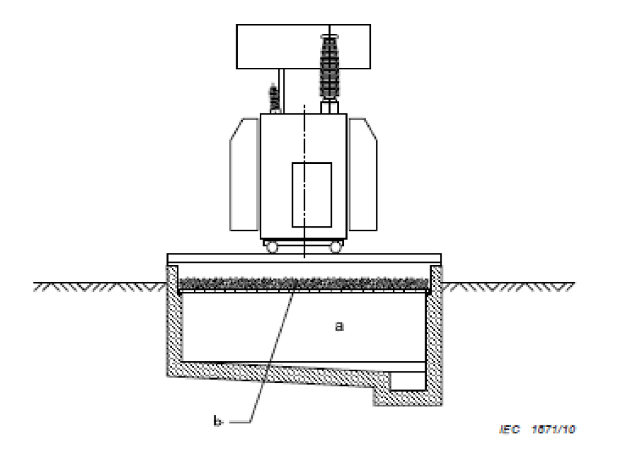
Key
a) Containment: the entire quantity of fluid of the transformer plus rain water
b) Gravel layer for fire protection see B.7-2
NOTE : In addition, the water from the fire-extinguishing installation arty) should be considered.
Figure 9 – Sump With Separate Catchment Tank
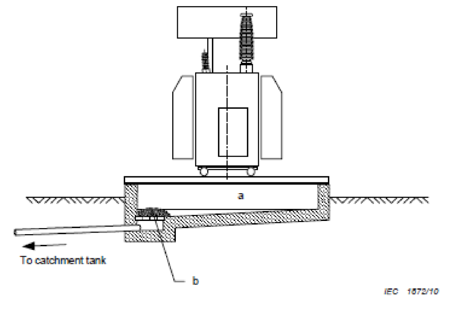
Key
a) Containment: minimum 20 % of the fluid from the transformer
b) Gravel layer for fire protection see B.7-2
Figure 10 — Sump With Integrated Common Catchment Tank
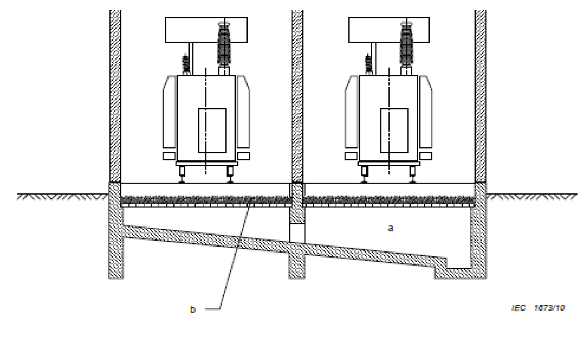
Key
a) Containment outdoor: the entire quantity of fluid of the largest transformer plus rain water Containment indoor the entire quantity of fluid of the largest transformer
b) Gravel layer for fire protection see 8.7.2
NOTE: In addition, the water from the fire-extinguishing installation if any should be considered.
Figure 11 – Example For Small Transformers Without Gravel Layer & Catchment Tank
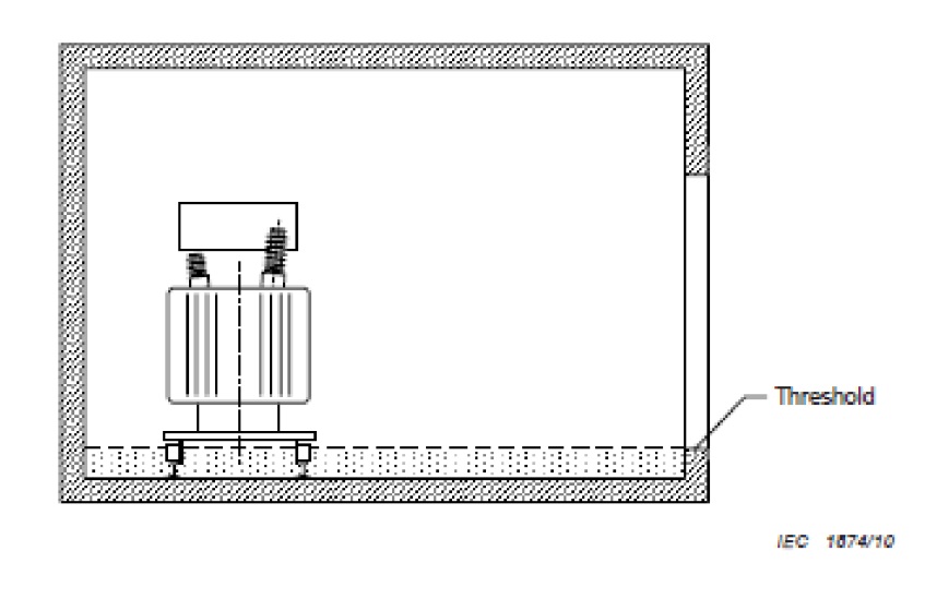
NOTE : The dotted area denotes the volume of the entire quantity of insulating fluid of the transformer spilled on the floor.
Further Reading
- Transformer Oils – 11kV 33kV 66kV Substation Transformer Oil Refilling, Sampling & Analysis
- Utilising Distribution Transformers To Optimise Solar
- 11kV Transformers | Introducing Amorphous Core HV Transformers
- VIDEO How To Verify Total Absence of Voltage By The Push Of a Button
- BundGuards | Substation & Transformer Oil Spills & Leaks Containment
THORNE & DERRICK SPECIALIST ELECTRICAL DISTRIBUTOR
The 11kV Specialists
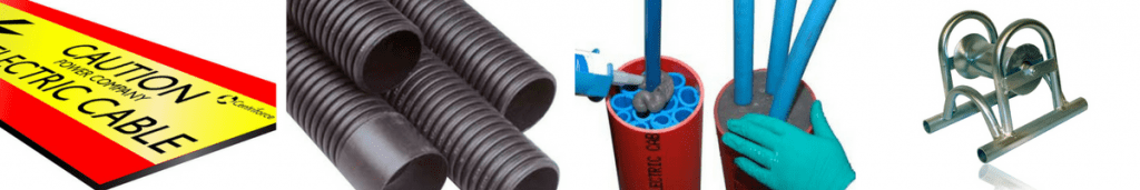
Thorne & Derrick distribute the most extensive range of 11kV Cable Jointing, Terminating, Pulling & Installation Equipment – we service UK and international clients working on underground cables, overhead lines, substations and electrical construction at 11kV and up to and EHV transmission and distribution voltages.
- Key 11kV Products: MV-HV Cable Joints & Terminations, Cable Cleats, Duct Seals, Cable Transits, Underground Cable Protection, Copper Earth Tapes, Cable Jointing Tools, Feeder Pillars, Cable Ducting, Earthing & Lightning Protection, Electrical Safety, Cable Glands, Arc Flash Protection & Fusegear.
- Distributors for: 3M Cold Shrink, ABB, Alroc, Band-It, Catu, Cembre, Centriforce, CMP, Elastimold, Ellis Patents, Emtelle, Furse, Lucy Zodion, Nexans Euromold, Panduit, Pfisterer, Polypipe, Prysmian, Roxtec.

LV – Low Voltage Cable Joints, Glands, Cleats, Lugs & Accessories (1000 Volts)

MV HV – Medium & High Voltage Cable Joints, Terminations & Connectors (11kV 33kV EHV)
Cable Laying – Underground Cable Covers, Ducting, Seals & Cable Pulling Equipment
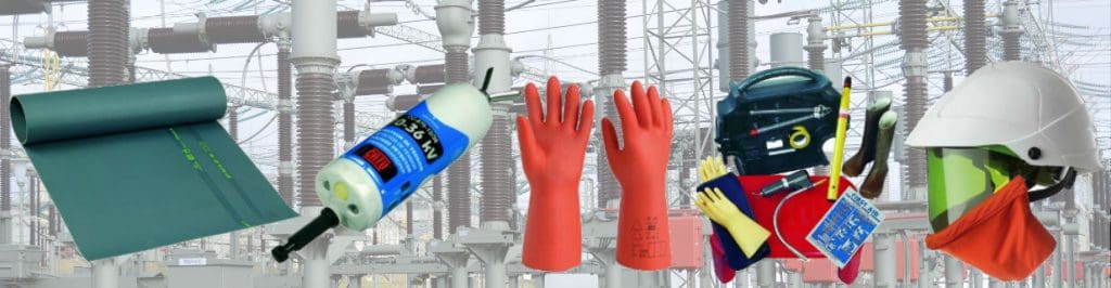
T&D, CATU Electrical Safety & Arc Flash Protection Specialists for SAP’s, Linesmen, Jointers & Electrical Engineers – Largest UK Stockist
Further Reading
-
 Transformer Bunds & Oil Filled Substation Transformers – BS EN 61936-1 : 2010
Size: 316.50 KB
Transformer Bunds & Oil Filled Substation Transformers – BS EN 61936-1 : 2010
Size: 316.50 KB
-
BS EN 61100 : 1993 IEC 1100 : 1992 Classification Of Insulating Liquids According To Fire Point
Size: 325.54 KB