

Introduction: Simplest High Frequency PWM With NE555


In this instructable I will show you how I made a high frequency Pulse Width Modulator with the most famous integrated circuit the NE555.
This circuit is a good starting point in electronics for beginners because of the low amount of parts. It can be used to regulate computer fans, LEDs, motors and much more.
Step 1: Demonstration
In this video you can see the finished project.
Step 2: High Frequency Pulse Width Modulation
I did not make the video.
Well if you watched the video you should now know what a PWM is but why do we need a high frequency ?
The reason is that with low frequency pulses going to a motor, you can hear the coils switching on and off and that can be quite annoying. Imagine you set your fan to low speed in order for it to be quiet and the aerodynamic noise indeed will decrease but the noise from coils will increase making it loud again!
But if the pulses are high frequency the human ear will not hear them.
Step 3: Parts List
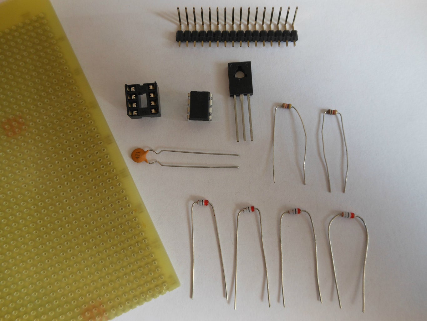
For this instructable you will need:
Perfboard
male headers (or just solder some wires)
1x - NE555
1x - 8 pin socket (optional)
4x - any general purpose diode (I used 1N4148)
1x - any power NPN transistor (I used BD139)
1x - 470pF capacitor
1x - 1 kΩ resistor
1x - 4.7 kΩ resistor
1x - Potentiometer 5kΩ to 1MΩ (I used 50kΩ) linear
Step 4: Schematic and PCB


A big advantage of this board design is that it can be plugged into the breadboard for testing.
HOW IT WORKS
This circuit can work on voltages from 4.5V to 16V. But if you used separate power supply for the chip and for the transistor it could be used for driving voltages higher than 16V.
The integrated circuit NE555 is wired in an astable mode(oscillator). The oscillation is determined by the size of capacitor(C1) and position of potentiometer(R3).
We have to use a transistor because the NE555 is not capable of supporting high currents to the load so the majority of current goes through transistor and not the IC. The PWM signal generated by IC switches the transistor on and off. In other words the PWM signal is amplified by the transistor.
The 1kΩ resistor(R1) limits the base emitter current, without it the path from pin 7 of the IC to transistor would act like short circuit to ground.
The 4.7kΩ resistor(R2) is a pull up resistor.
For the schematic and PCB I used a free program CadSoft Eagle which I would recommend to anyone making schematics or PCBs.

Step 5: Conclusion


This circuit is good for controlling speed of a motor but if you try to use this to dim LEDs it will work to some extent but you won't be able to fully dim the LED, although it's not that horrible, just try it yourself.
If you manage to build this project don't forget to post your results into the comments.


