 da
da de
de es
es fr
fr it
it nb
nb nl
nl pt
pt sv
sv fi
fiSpeed Sensors & Rings: A Complete Guide
We are now accustomed to speed sensors located in the periphery of the wheel bearings, but this was not always the case. Before ABS was introduced, the vehicle speed was often measured directly at the gearbox or differential. Later on, the sensors moved to the drive shafts and then to the wheel bearings. Numerous variants have been used over the years. So we will discuss these variants and their characteristics one by one.
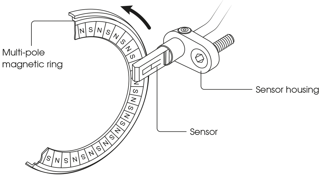
Different types of sensor ring
The ABS system uses sensor rings to allow the speed sensor to register the rotations. These rings have metal teeth or alternating magnetic poles that generate a signal.
However, because the toothed ring did have some inherent disadvantages (weight, faults caused by dirt and damage) and because subsequent development made greater accuracy and functionality desirable, manufacturers switched to a magnetic ring on the wheel bearing itself. The ring is so neatly integrated in the design that you can no longer see whether a wheel bearing has an ABS function or not.
The fact that the magnetism had now moved from the sensor to the sensor ring opened up opportunities for further development of the speed sensor.

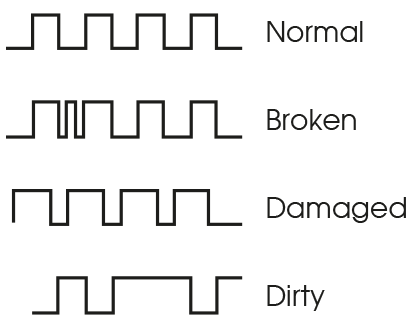
Dirt on or damage to the sensor rings can make the signal deviate, which can cause strange faults. So we strongly recommend that you check the sensor rings thoroughly first in the event of a malfunction!
Passive sensors (DF6)
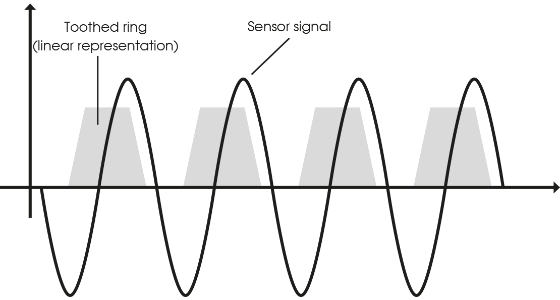
Until about 2003, vehicles were mainly equipped with passive wheel sensors, also known as DF6 sensors. This type of sensor is always used in combination with a toothed metal sensor ring. The sensor itself contains a permanent magnet with a coil around it.
When the wheel turns, the teeth in the ring create a variable magnetic field, which generates a constantly fluctuating voltage in the coil: a sinusoidal analogue voltage signal is transmitted to the ABS ECU. The higher the rotational speed, the greater the amplitude of the signal. At very low speeds, however, the amplitude is so small that the ABS ECU does not detect a signal. So you should assume that the signal is only strong enough from about 20 mph.
Both the passive sensor and the toothed sensor ring are fairly easy to test yourself. Many diagnostic systems can show live wheel speed data. If you don’t have access to this type of diagnostic equipment, an oscilloscope can help as well: check the sensor signal by connecting the sensor's signal wire to the oscilloscope. Now turn the wheel: you should see a sinusoidal signal (usually 0.5V - 1.0V). Look carefully for irregularities in the signal, caused by damage to one or more teeth. If you only want to check the sensor, quickly pass a metal screwdriver across it several times. Although the shape of the signal doesn't tell you much, this check indicates whether or not the sensor is capable of responding.
Active sensors (DF10)
Since 2003, many car manufacturers have switched to active wheel sensors. Knowledgeable specialists refer to this first version as the DF10 sensor. This type of sensor is much more accurate and no longer speed-dependent: each pulse is of equal amplitude, so all speeds can be measured (also the stationary state of the vehicle). This type of signal is often referred to as a block signal.
Although DF10 sensors offer many advantages over the older DF6 standard, these sensors were still used with toothed rings at first. Consequently, these sensors also contained an internal magnet for generating their own magnetic field. After 2006, the use of a magnetic ring became increasingly common in these systems. As a result, these sensors no longer required an internal magnet.
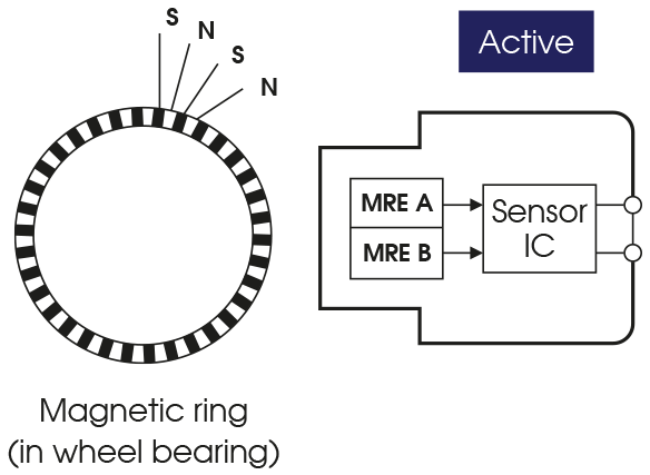
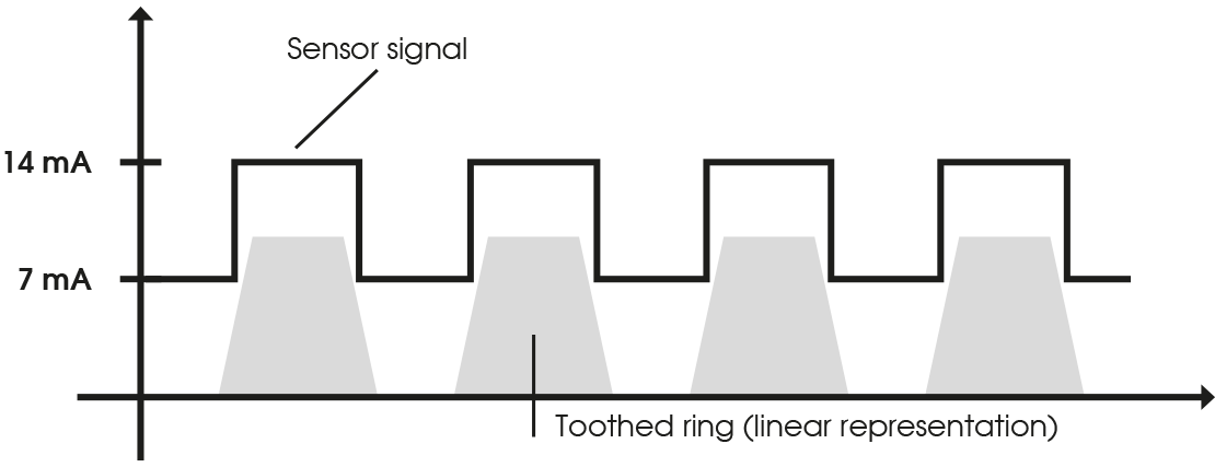
The DF10 sensor requires a voltage to operate, which is why they are called active sensors. The sensor has two wires: the first for the power supply (often 12V, but occasionally 5V) and the second for ground. The signal output to the ABS ECU runs through one of these wires: this differs per car. The sensor contains a semiconductor, also called a Magneto Resistive Element (MRE), which can function as either a conductor or an insulator. When the sensor ring rotates, the semiconductor alternately switches the output signal (high/low). This generates a digital square-wave signal, which is sent to the ABS ECU. This signal can be displayed with an oscilloscope.
Useful values to aid diagnosis:
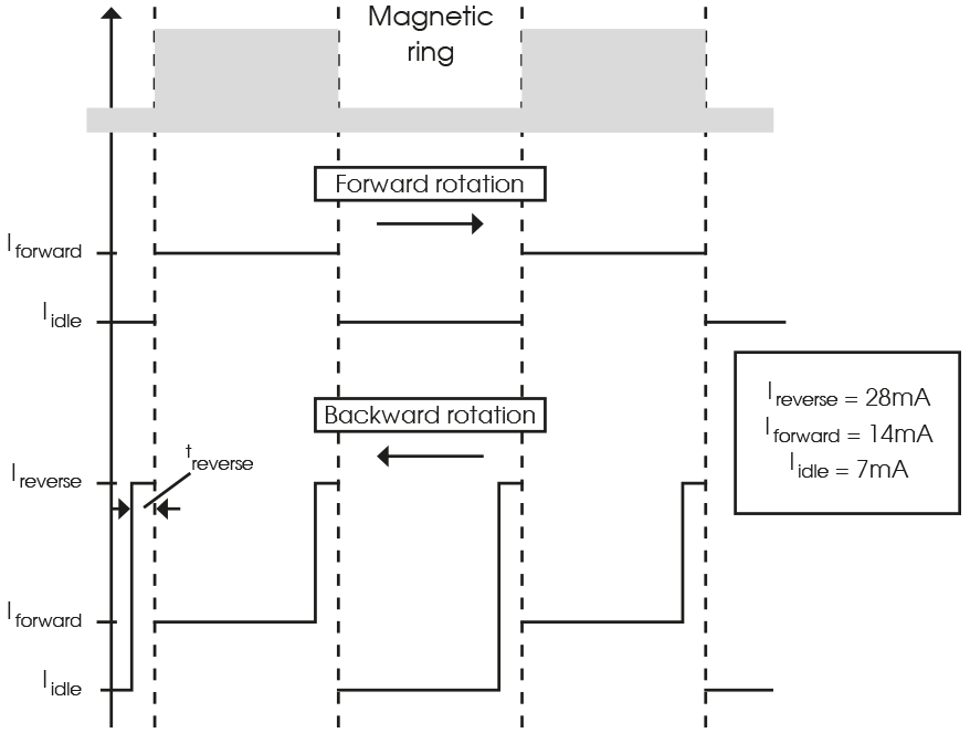
As shown in the diagram below, the block signal has a fixed value of 7mA, 14mA or 28mA. A welcome addition to the existing functionality was the ability to make driving backwards visible. This led to the creation of the DF10-RotDir. In addition to the standard block signal, this sensor is capable of sending an extra signal when the vehicle is reversed.
Greater intelligence (DF11i)
As CAN and other communication systems started to be used extensively elsewhere in the vehicle, people realised that a signal from a speed sensor could provide much more information than just the rotational speed. In addition to the direction of rotation, for which the DF10-RotDir already offered a neat solution, an additional check of the available magnetic field could now also be built into the signal.
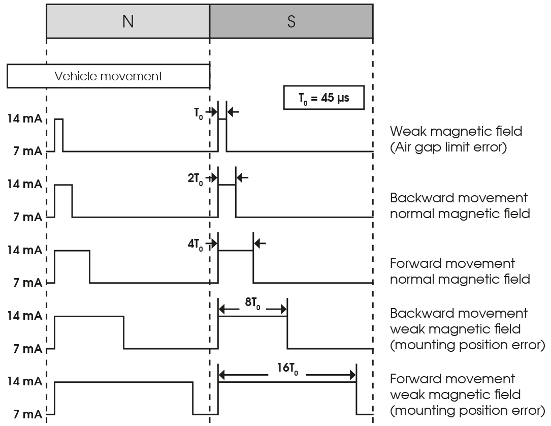
To make this possible, the speed sensor had to be able to generate different signals for different situations. This led to the introduction of PWM: Pulse Width Modulation. The principle underlying this protocol is actually very simple. A standard length is determined for the pulse (in the case of the DF11i this is usually 45 μs) and subsequent extension of the pulse by a factor of 2, 4, 8 or 16 makes it possible to communicate extra information to the ABS ECU, in addition to the time when the pulse is actually generated. The diagram explains this principle more clearly.
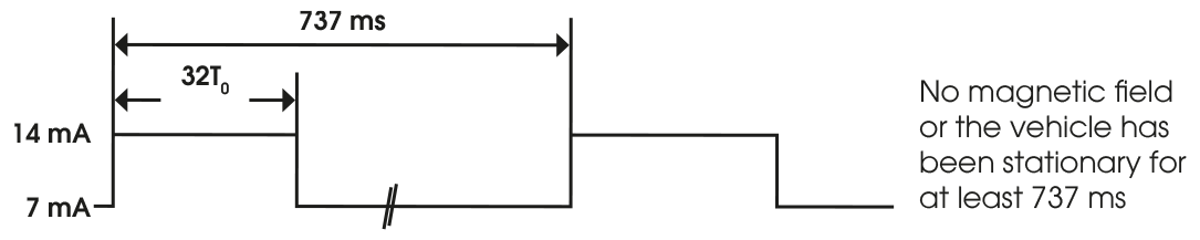
In addition, DF11i sensors were ‘programmed’ to include another smart function: the difference between zero speed and a non-functioning sensor. When the vehicle is at standstill, a DF11i will still periodically send a pulse to the ABS ECU to indicate that the sensor is still operational. This generally occurs every 737 ms in the form of a pulse that has been extended by a factor of 32.
Interesting information:
You will probably be asking yourself why the names of all these sensor types start with ‘DF’? This modern sensor technology was originally dreamed up by the clever people at Bosch GmbH: ‘DF’ stands for ‘Drehzahlfühler’, which is German for speed sensor.
The DF11i was even produced in a version with an internal magnet to make it suitable for applications that still used the old-fashioned toothed ring (like a number of versions of the DF10). This type is called the DF11iM. In the figure, an exploded view of this particular sensor, ‘M’ is the magnet.
The new standard (VDA)
Due to developments, such as 'PSI5' for the airbag system among others, the speed sensor has been able to make the transition to an even higher level of sophistication The VDA sensor is a clear move away from the practice of generating a single pulse. Instead, this sensor generates a 9-bit message after the pulse, distinguished by the fact that the pulse amplitude is twice as high as that of the bits. This not only makes it possible to transmit extremely specific information, it also allows the sensor to be programmed. The protocol that is used for this is called the ‘AK protocol’. We know that certain Infineon sensors operate according to AK protocol 4.0, which was released by Daimler AG in February 2008, but newer variants are now also in use.
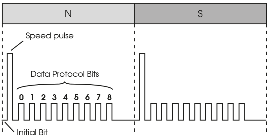
You are probably asking yourself what these 9 bits actually do. Unfortunately, we can only give you a partial answer. Most of the bits are freely programmable, so the function can differ per car brand and model.
Always use original wheel sensors when replacing!
ACTRONICS recommends always choosing OEM when replacing the wheel sensors. These sensors must be selected by chassis number, because there are many different types available that all look alike on the outside. The ECU will then usually give error codes related to the 'impedance' of the wheel sensor.
Contamination, damage and backlash on wheel bearings
In the event of wheel sensor complaints, always check the wheel bearings for contamination, damage and backlash. The signal that the ring has to generate has little tolerance and a small deviation can therefore immediately cause a malfunction.
Measuring wheel sensors yourself
Luckily, all these different types of wheel sensor can still be tested with an oscilloscope. Simply by spinning the wheel fast with the ignition switched on (important!), you can easily assess whether the sensors and sensor rings are still working properly. Obviously, you can also use a metal (= toothed ring) or magnetic (= magnetic ring) screwdriver. However, you do need to properly assess the resulting signal. So you should always use a typical signal for comparison. We have put together a brief summary for you to further clarify the differences between these signals:
DF6
A sinusoidal signal, generally between 0.5V and 1.0V. The amplitude increases as the wheel turns faster.
DF10
A block signal with a fixed amplitude of 7mA, 14mA or 28mA. The frequency of the block signals increases as the wheel turns faster. Types with the RotDir function generate a two-level block signal when rotating backwards.
DF11i
A PWM signal with a signal duration of 45 μs. When rotating forwards, this signal is extended by a factor of 4, so the ‘signal block’ should be 180 μs in duration. When rotating backwards, the signal block is extended by a factor of 8, i.e. a duration of 360 μs. When the wheel is stationary, the sensor generates a signal block with a duration of 1440 μs (32 x the base signal) every 737 ms. So there is always a measurable signal.
VDA
A VDA sensor generates a speed pulse when the wheel turns, followed by a 9-bit signal. Factors such as the direction of rotation are included in this signal. If the wheel is stationary, the signal will still be sent, but without the speed pulse. So there is always a measurable signal.
NOTE: In some cases, different sensors are used for the front and rear wheels. So make sure you do not switch the positions of these sensors!