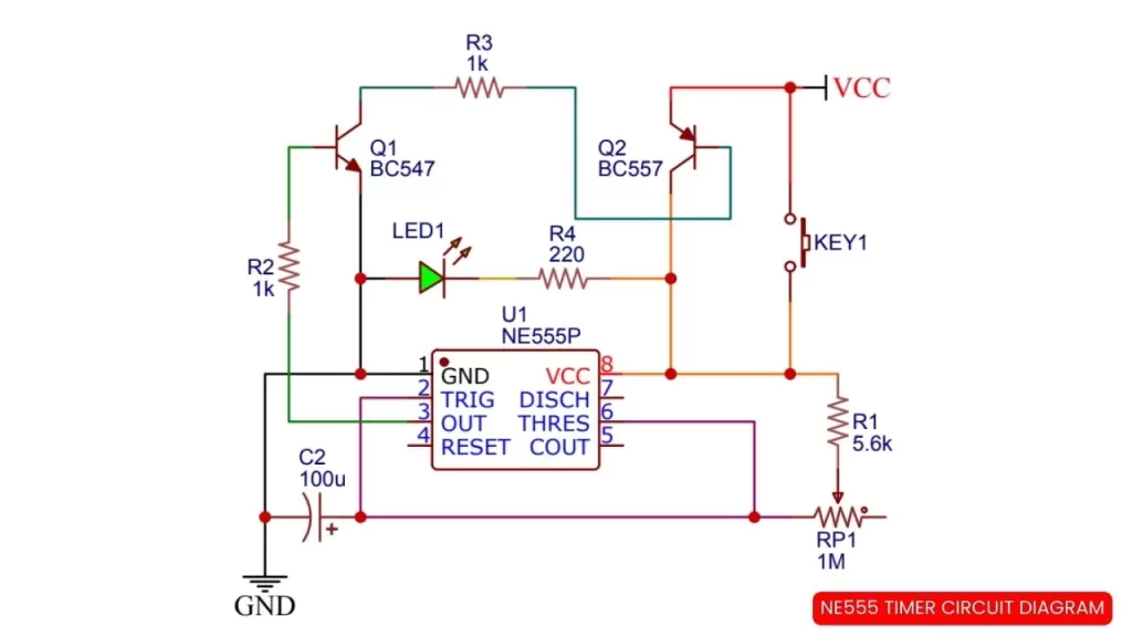
Here is the circuit diagram and components list of NE555 timer. The timer circuit will start working if you push on the push button. In the same time of pressing push button the Connected LED turn on.
After releasing the push button, the LEd will turn off after some seconds. The delay turn off time can be change by adjusting the potentiometer.
NE555 Timer circuit diagram
Components Required
- NE555 IC
- BC547 Transistor – 1
- BC557 Transistor – 1
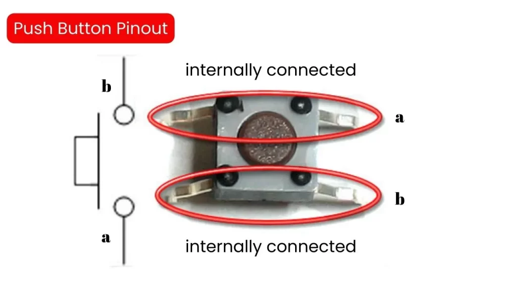
- Push Button – 1
- 1M Preset pot – 1
- 100uf/25v capacitor – 1
- 1K resistor – 2
- LED – 1
Components Pinout
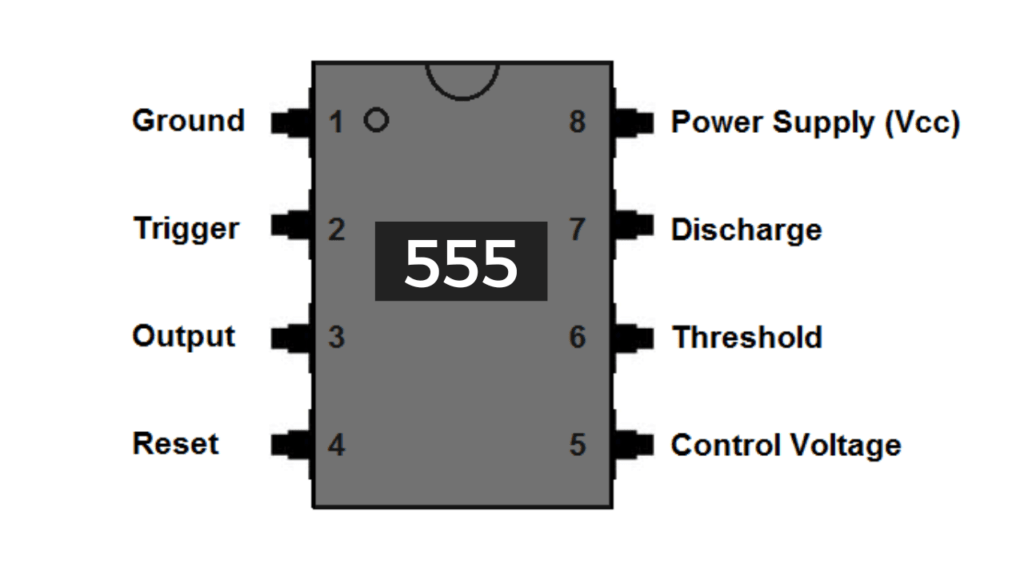
NE555 Timer IC PInout Diagram
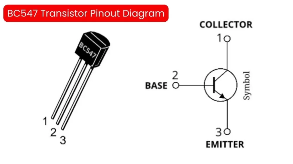
BC547 NPN Transistor Pinout Diagram
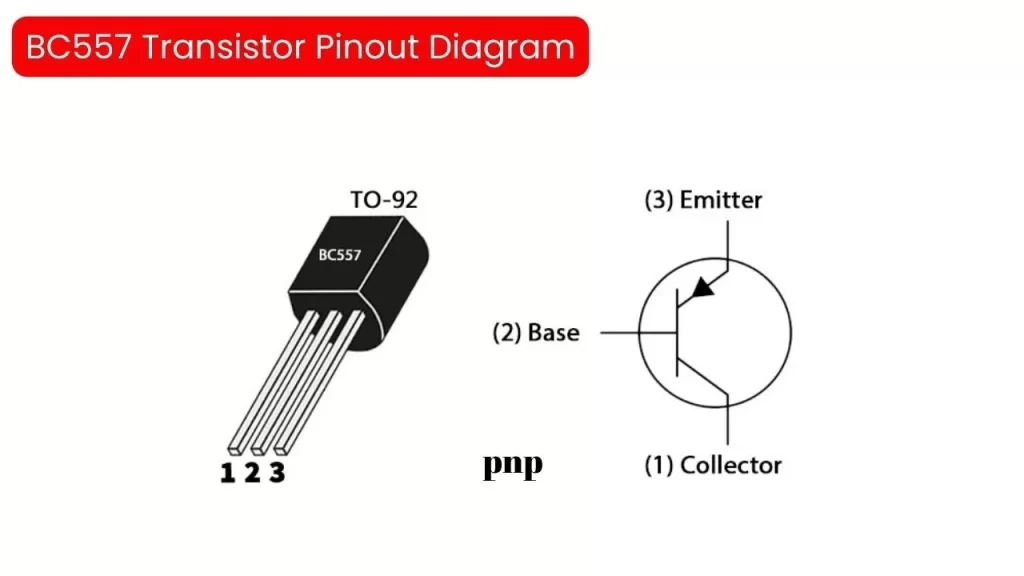
BC557 PNP Transistor Pinout Diagram
Push Button Pinout Diagram