The impedance of an End Fed Half Wave (EFHW) dipole falls in the range of approx. 2k…4k Ohm. Using a transformer is one way to match it to the 50 Ohm transceiver output.
There are many suggestions of how to build such transformers. Here is my version, grown over the years by performing many experiments as well as following the discussion on the SOTA reflector.

Rules of thumb
Amidon 43 mix is not ideal for shortwave. 4C65 from Ferroxcube or Amidon 61 mix would be favourable (details will follow later). Nevertheless the 43 mix is used for most transformers I have seen and it works somehow. The following rules are valid mainly for this material mix but may work for others as well.
- If you are using a QRP radio up to 10 watts, one or two (stacked) toroids, such as FT82-43 or FT50-43 are sufficient. For more power, use larger toroids and stack them.
- 3 primary turns are favourable when using small toroids. For larger toroids such as FT140 or larger, two primary turns are enough (due to the higher AL of FT140 and above).
- If you prefer the bands below 20MHz, it’s possible to build an autotransformer instead of twisted primary and secondary windings (less effort).
- For the bands up to 20m, the capacitor for compensation is not mandatory.
- A turns ratio of 3 : 21 (i.e. transmission ratio 1 : 49) seems to be more suitable for ‚portable‘ EFHWs deployed at low heights. This is because the vicinity of ground will cause the antenna impedance to be closer to 2k Ohm than to 4k Ohm.
- A compact and continuous secondary winding is advantageous over the often shown ‚cross-over style‘ by W1JR. It has advantages for other purposes but for a transformer, the coupling has to be as good as possible. A turn which runs loosely through the toroid’s centre, as it does with the cross-over technique, introduces stray inductance, leading to additional loss.
Here is a (more or less) chronological summary of my experiments:
1. First steps with FT140-43
As a starting point I simply copied the design of a broadband transfomer, using a ferrite toroid FT 140-43 from Amidon with a turns ratio of 3:24. The transmission ratio, which is the square of the turns ratio (1:8), is 1:64. This means an impedance of 3200 Ohms will be transformed to 50 Ohms. The above mentioned range of 2k to 4k will fall in a range of approx. 30 to 60 Ohms which results in a slight (but acceptable) mismatch. There are several manuals available, e.g. here or here.
I used 1mm enamelled copper wire, primary and secondary winding are twisted. The bare toroid is covered with an ultra thin teflon tape in order to avoid damage to the wire’s insulation. The cross-over winding technique as shown below is no longer recommended! Two 68pF capacitors in parallel are used for compensation on the primary side.
The VSWR from 7MHz to 14MHz is < 1.5:1 with a load resistor of 3 kOhm.

2. Variants with smaller FTxx-43 toroids
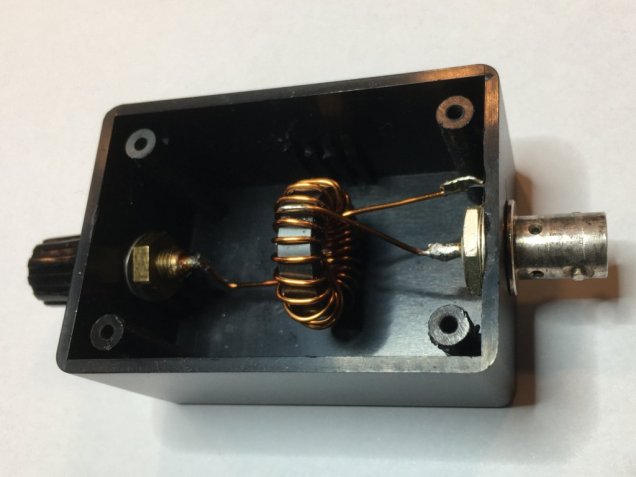
Later I built another transformer 1:64 with the smaller toroid FT82-43. The turns ratio is again 3:24 but this time I built an auto-transformer (see photo below).
With a resistive load of approx. 3.3 kOhm, between 7 MHz and 14 MHz no capacitor is required. The reactive component of Z is almost negligible and VSWR is below 1.5 : 1.
I had some concerns about saturation of this tiny toroid but up to 10 watts it seems to be working ok.
In the meantime I worked ZL1TM for my all time ODX from a SOTA reference with my EFHW-dipole and this transformer.
Another variant with a tiny FT50-43 toroid for ultra-light equipment can be seen here.
An interesting manual written by Heinz, HB9BCB, can be found here
3. Variant with CST16/7.9/14-4S2 from Ferroxcube
This toroid is available from DX-wire. The material properties of 4S2 are somehow comparable with the Amidon 43 mix. What makes this toroid interesting is its cylindric shape which could otherwise be achieved by stacking two or three toroids.
I opted for an 1:49 transformer with 3:21 turns ration. There is a tap after the third turn (auto-transformer), so no twisting of wires. The frequency range of interest is 7MHz to 14MHz because my MTR-3B only works on these bands. VSWR was < 1:1.5 with load resistors in the range of 2.2k to 3.9kOhm.
For the first time I made a second (identical) transformer and tested them ‚back-to-back‘ in order to get an idea of the system loss. The result looked promising: -0.8dB from one end to the other, means -0.4dB for one transformer, which equals a power loss of < 10%.
Power handling capability is up to 10 watts.


4. Experiments with Tx36 – 4C65 from Ferroxcube
I never really questioned the design with the Amidon 43 mix but had the feeling that it isn’t the best choice. In a discussion on the SOTA reflector about more suitable materials someone suggested the Amidon 61 mix for use in broadband transformers. Its loss @ 10 MHz is approx. 4 (four) while 43 mix shows a loss of about 220 (two hundred twenty!) in the same frequency range (s. graph below).

A big enough toroid with 61 mix wasn’t available, but a Tx36 – 4C65 from Ferroxcube. This material mix has a slightly lower loss than Amidon 61.
Baseline: Transformer with FT140-43
As a base line I used the design of my first transformer:
- AL = 885nH
- 3 turns primary
- 24 turns secondary
Then I tried to scale the known design to the properties of a Tx36 – 4C65 toroid. My goal was to keep turns ratio and inductance the same.
Design with Tx36 – 4C65:
It soon turned out that the number of turns (seven primary and 56 secondary) wasn’t feasible.
So I started with five turns primary. The impedance of the primary winding at 7MHz wouldn’t be as high as intended, but reached 200 Ohms which should still be sufficient.
- AL = 170 nH
- 5 turns primary
- 40 turns secondary
With this approach, however, it wasn’t possible to achieve simultaneously good matching on the bands from 7 MHz to 14 MHz with a single fixed capacitor.
Only with a turns ratio of 4:32 all three bands could be matched. A capacitor of 200pF was required for compensation on the primary side. It worked also with a turns ratio of 3:24, but the impedance of the primary winding was now down to 67 Ohms. This seemed a bit low and in order to avoid trouble I went back to 4:32.

When I tested the transformer in combiation with the EFHW dipole, the VSWR was >2:1 on all bands. Apparently the impedance of the end fed dipole was lower than the assumed 3000 Ohms, resulting in a resistance of about 30 Ohms on the primary side PLUS some reactance, varying from band to band. Surprisingly it wasn’t an issue with the FT140-43 toroid in the very same antenna setup.
The most promising option was to reduce the turns ratio of the transformer to 4:28. With a load resistance of 2.5 kOhms and 2 kOhms the VSWR was now 1.2:1 on all three bands. The measurement with the real EFHW dipole however, resulted in an even worse VSWR. The reason is not yet fully understood but due to the lack of ideas there is currently no solution with this material mix.

Hi Roman, thanks for sharing. I enjoy reading your posts.
Thanks for the kind feedback, Andrew!
I enjoyed the experiments and writing the summary afterwards 🙂